What is Fit in Engineering?
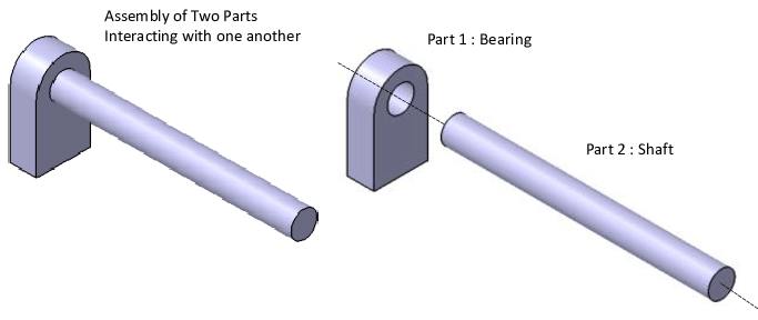
In the mechanical engineering aspect, the fit is the connection between two mating components of a device or framework. This bond comes from this correlation. It is usually contrasted with the assembly’s operability and durability. The Fit is key since all pieces, such as shafts and hollows, springs and cylinders, or nuts and bolts, must have perfect coordination even if they have to glide past each other gracefully or firmly stick together.
Fits can be split into two classes. They are based on things like whether the interference or clearance between components is a hindrance or a source of attraction. Take the “tight fit” for example. It is relevant if parts stay well connected and in one place, such as at a press-fit bearing assembly. Alternatively, a “loose fit” may enable the parts to move in freedom, like in the bearing bearing a shaft to rotate.
The fit of parts defines how they work, such as slide, roll, or lock. As a consequence, tasks of fit design are not only confined to good design but also to constructing hinges that would fit them, and hence, guarantee long-term application. Engineers use different ways to assemble parts. This enhances the design’s mechanics and functionality by applying the right fits.
Basics of Fits: Hole and Shaft Systems
Mechanical engineering requires precise fittings. They enable the assembly to work and to last. The two systems that are typically used to standardize these fittings are the hole and shaft basis systems. So, each system creates a structure for the achievement of various degrees of loose or tight fit using appropriate tolerances.
Hole-Basis System
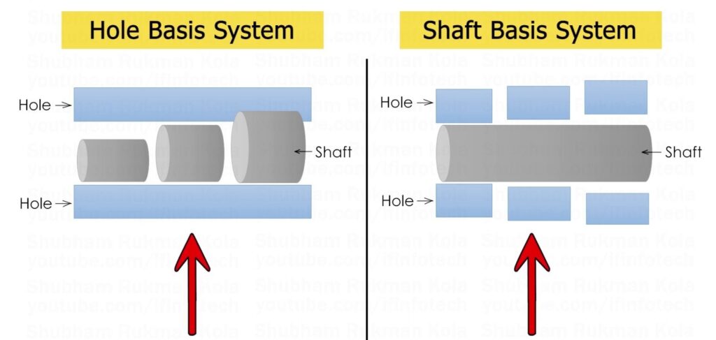
This is the most frequently used technique in the field of engineering customizations. The hole diameter is the same and uniform in the used system, which is the base of all sizes. After that, the dimensions of the shaft are adjusted to make sure it has the required fit. It could be an easy fit for clearance or a tighter assembly with an interference fit. The standard hole’s dimension is used for its smallest size, with a minimum deviation equal to zero. This way is preferred as holes can always be drilled to the right size using standard drill bits and reamers.
Shaft-Basis System
Unlike the hole-basis system, which fixes the shaft’s diameter, the shaft-basis system keeps the hole’s diameter as the basic dimension. Changing the size of the hole makes the shaft fit the hole properly. This system is ideal where the shaft cannot be made after its initial production, such as in pre-finished shafts or those which require precise balancing for high operating speed. Here, the basic size is the shaft’s measurement, with +/- 0 in the upper deviation. This method may be rare but it is very important in applications where semi-finish or material pre-sizing should be done.
How to Name Different Fit Types in Mechanical Engineering?
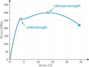
In mechanical engineering, naming different fit types accurately is pivotal for selecting appropriate fits during product assembly. The naming conventions are standardized by the International Organization for Standardization (ISO) through an alpha-numeric code system. This system not only identifies the type of fit but also communicates its tolerance levels.
The code is divided into an alphabetic and a numeric section. The alphabetic portion distinguishes whether the specification refers to a hole or a shaft. Upper-case letters indicate holes, while lower-case letters are used for shafts. For example, the code “H7/h6” reflects:
“H7” is the tolerance range for the hole.
“h6” is the tolerance range for the shaft.
This standard coding lets engineers easily find the largest and smallest sizes for both the hole and the shaft. It helps with precise assembly and ensures parts fit together.
Types of Fits
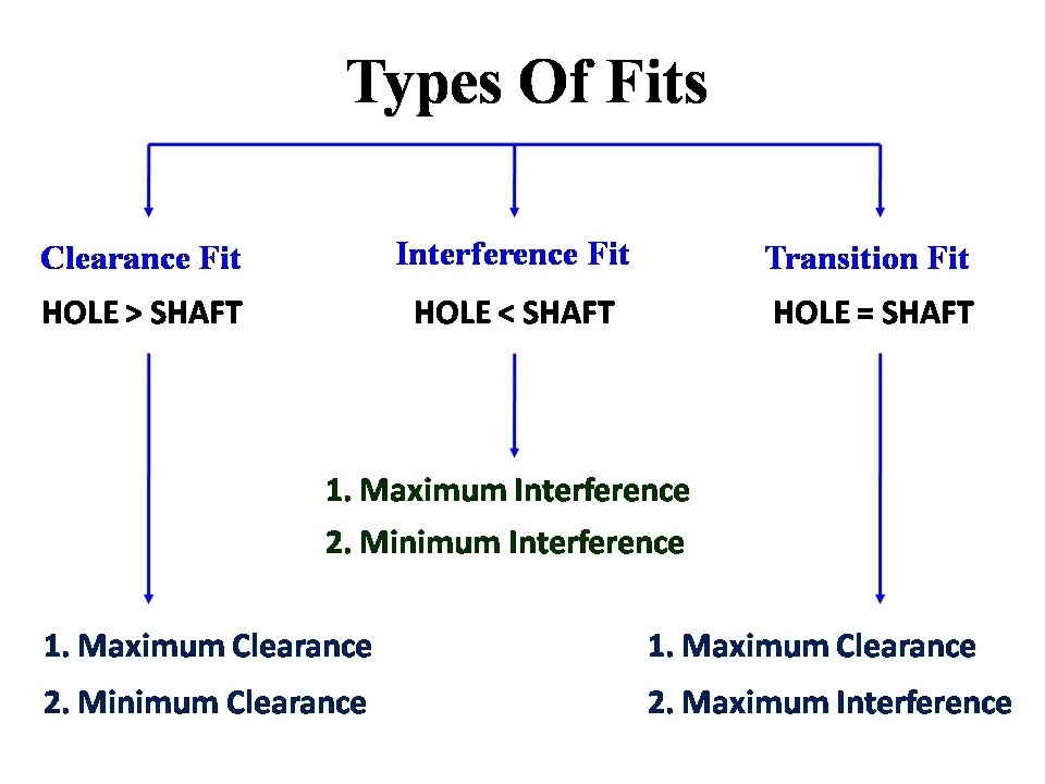
In mechanical engineering, the term fit refers to how close the tolerance is between two mating parts. This relationship can determine how well and easily the parts will go together. Picking the right fit is important because it affects how well things work and how long they last. In engineering, there are three types of fits: clearance fits, interference fits, and transition fits. These categories have different purposes which are chosen depending on what mechanical requirements need to be met for a given application environment.
Clearance Fits

In a clearance fit, there will always be a space between two mating parts; this means that the hole is larger in diameter than its corresponding shaft. The main aim of this type of fit is to ensure easy assembly and disassembly while allowing movement between components.
Types:
- Loose Running Fit: Used where accuracy is not critical and some contamination is possible. The minimum clearance for a 25 mm diameter is 0.11 mm. The maximum is 0.37 mm. Typical uses include dusty or corroded places and bending hinges.
- Free Running Fit: It’s for uses with temperature shifts and high speeds. For a 25 mm diameter, it gives clearances from 0.065mm to 0.169mm. It’s common in shafts with plain bearings and little rotation.
- Close Running Fit: Provides small clearances for moderate accuracy. They are for medium speeds/pressures. A H8/f7 fit gives 0.020mm minimum clearance. The maximum is 0.074mm. This is for sliding rods in machine tools and spindles.
- Sliding Fit: It keeps small clearances when precise relative movement of sliding parts is needed. An H7/g6 fit for a 25mm shaft has clearances from 0.007mm to 0.041mm. This is ideal for guiding shafts, sliding gears, slide valves, car parts, and clutch discs in machine tools.
- Locational Clearance Fit: It gives very small clearances. No significant movement will occur between parts after they are positioned accurately. A H7/h6 fit for a 25mm diameter offers a minimum clearance of 0.000mm and a maximum of 0.034mm. These fits are typically used in roller guides and to guide shafts precisely.
Transition Fit
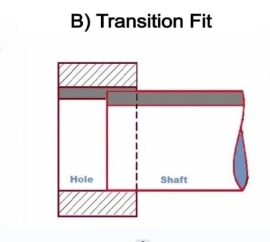
A transition fit can give clearance or interference based upon individual tolerances of the specific parts. This property makes it adaptable to scenarios that need some movement precision. They also account for tolerances.
Types:
- Similar Fit: Allows minimal or visual clearance, plus it is thrown together and assembled with a rubber hammer without a lot of force. This design could work well for such components which require precision in terms of alignment but are not in the range of high loads. For a 25 mm size of a H7/k6 a gap value of 0.019 mm at the most and 0.015 mm interference at the most. It could be used for hubs, gears, pulleys, and bearings buildings.
- Fixed Fit: This fit offers a precise alignment with minimal clearance, requiring light force for assembly. It suits permanent setups but allows easier disassembly. For the mentioned 25 mm diameter, the H7/n6 grade allows a 0.006 mm clearance and a 0.028 mm difference. This form fits are often used with tapered bushes, plugs, couplings, and sleeve bearings.
Interference Fit

An interference fit (also known as a press fit or a friction fit) requires the shaft to be bigger than the hole. This allows the use of force or special treatments like heating or cooling for assembly. This connection is utilized when a high-strength tight bonding is needed to transfer power or can bear a shear load.
Types:
- Press Fit: Non-coating interference fit is perfect for devices such as the hub and balls. Possible interruptions are as minimal as 0.001 mm for a diameter of 25 mm. This is among the thinnest inserts commonly used for saddle grids on shafts and hubs.
- Driving Fit: Demands to increase the number of assembly forces adjusted, to be used for a positive engagement of gears and shafts. This should be applied to all the maximum and zero minimum intersections from 0.014 mm to 0.048 mm. This type of tool can be used for permanent mounting of shaft and gear.
- Forced Fit: High interferences fit being subjected to the advanced assembly technique approach, making a permanent assembly process becomes the most likely path. The joint line does not give a significant shear area. So, the bore diameters of a 25 H7/u6 fit have a 0.027 mm minimum interference and a 0.061 mm maximum. They are good for mechanical uses like putting wheels on railway axles or heavy gears. These parts must withstand dynamic and axial forces.
How to Achieve Dimensional Tolerances for Fits?
Tolerance is vital. They allow for the factor of elastic size and shape variations. Yet, the assembly can still hold even if the parts are not the exact same size. Creating tolerance limits lets engineers consider small inaccuracies. These are normal in manufacturing. The limits assure high product quality by guiding assembly.
CNC Precision Machining
CNC (Computer Numerical Control) precision machining is a baseline method for achieving incredible deviation, which is very important for increasing productivity or expanding business in the industrial sector. Using these controls, the extra zone can be +/- 0.001mm on CNC machines. They ensure that the parts are right and that production matches the specs. Machinists can select the best tools and fixtures. This lets them make parts that fit into complex assemblies. The assemblies are the main parts of the system. They let the system work.
Grinding
Grinding is the default method for making parts. This is especially true for the highest accuracy, up to +/- 0.25 microns. This accuracy notably matters for such cases where the end product requires a tolerances interface fit. Even a small variation of tolerance will lead to substantial errors. Grinding lets the manufacturers set a higher standard than usual. It also lets them get the needed alignment quality, conformity, and reliability.
Reaming
Reaming can make very tight pores. They are a key part of many engineering projects. The EDM process is noteworthy. It can remove just enough material accurately. This is important for achieving tight tolerances in mechanical fittings. Precise reaming is vital. It allows holes to fit. This minimizes stress and misalignment in the final assembly.
Adherence to GD&T Standards
Manufacturers have to follow GD&T (Geometric Dimensioning and Tolerancing) standards because the standards describe the maximum deviation that the part can have from the true geometry. These people are in charge of manufacturing. They guide as each issue remains within the design’s specs.
Application of Fits in Engineering
Application Requirements
Every engineering fit is designed for a specific task and application. Consequently, your is to clarify the objective. Take the question of how the pattern is supposed to perform, whether it is due to the delicate or strong purposes. Distinguish the roles of various parts in terms of the product that is supposed to be complete with the device itself being functional.
Budget Considerations
Engineer-made fits can have huge differences in cost, particularly when dealing with cases that are complex and require accuracy. Loose tolerances tend to create higher costs. By the way, a good way to start is to perform a budgetary evaluation. Balancing cost and function efficiently in production is crucial for maintaining dimensional tolerances within budget.
Understanding Tolerance
The notion of intolerance (quickness) is the key idea in picking a good engineering fit. Decide in how much the flexibility or rigidity should be in order to match the demands of your site. Determine if rotation of the segment is required fully or does not have to be held tight. Making products with slight differences can reduce measurement precision. This is crucial when assembling components to ensure they meet standards and don’t exceed tolerance levels.
Conclusion
In the world of engineering, precision is paramount. From clearance fits to interference fits, each type serves a distinct purpose in ensuring optimal performance and longevity of mechanical assemblies. By understanding tolerance, cost, and needs, engineers can create solutions. The solutions meet high standards for quality and function.
Partner with us to improve your engineering fits. This will raise your assemblies to new levels of precision and reliability. Let’s collaborate to engineer solutions that surpass expectations and set new standards in the industry.
FAQS:
What are LMC and MMC?
MMC is the term used in the assembly tolerance conversation. LMC is about holes in housings. It’s about holes near the edges and the thickness of pipes.
What is Allowance?
Tolerance in mechanical engineering is the planned difference between the dimensions of the hole and the nominal diameter of the shaft. It is computed by LLH – HLS, where LLH is the hole’s lower limit and HLS is the shaft’s higher limit. To determine the fit with regard to clearance and sticking, the formula is applied. The positive sign for clearance and the negative sign for sticking are both considered a good fit.
Why is the Hole Basis System is most commonly used than the Shaft Basis System?
The hole basis setting is most suitable compared to the shaft basis setting because it eliminates the complications that are associated with production. Machine shops that utilize one tool which can be set up to create standardized holes across various shaft sizes will see overall, products being manufactured faster and at a lower cost.
How do We Calculate Engineering Fit Tolerance?
Engineering fits are determined and represented by dimensional drawings from the ISO- as well as ASME standards, which define the detailed dimensions and tolerances for various fits and their corresponding hole as well as shaft sizes.
What are Tolerance Grades?
Tolerance grades in engineering indicate component accuracy levels across 18 grades:
- IT01 to IT4: Used in high-precision instruments like gauges.
- IT5 to IT7: Applied in precision engineering fits.
- IT8 to IT11: Employed in general engineering.
- IT12 to IT14: Utilized in metal working.
- IT15 and IT16: Used for general cutting and casting tasks.