What are CNC Machining Drawings and Their Importance?
CNC machining drawings are the jewels upon which CNC machines depend so much for bringing designs into real life. These part drawings and machining blueprints that are included as sets provide all the details with every dimension, tolerance, and specification needed for the production of parts with the highest level of accuracy. By following the designs of manufacturing process drawings, CNC machines can accomplish the transformation of raw materials into the complex components that the industries demand, of which accuracy is the most important.
The technical drawing samples especially engineering drawings and machining blueprint symbols are the biggest resources in the manufacturing field. While these CNC drawings and technical designs do the automatic part of machining, they also maintain the standard and quality during production. Equipped with these precise manufacturing drawings, engineers and machinists can close the gap between theoretical designs and physically manufactured products, thereby helping speed up and enhance the manufacturing process.
Differences between CNC Machining Drawings and Traditional Drawings
CNC Machining Drawings
For precision manufacturing, CAD software produces CNC machining drawings that can create complex engineering drawings with stunning accuracy. These digital plans make it possible to show technical details, and thus all the information needed for the design is communicated: from outlines to complex geometry. This level of detail is critical in CNC machining as ensuring the dimensions and tolerances specified is what will guarantee the success of the final product.
Traditional Drawings
In contrast to the traditional hand-drawn blueprints, which are laden with historical and aesthetic values, but are sometimes too crude to design exact machining details. Although these sketches depict the spirit of design through artistic representation, the unforeseen imprecision of hand drawings makes it difficult to conform to the technological requirements of precision manufacturing. Drawings of such type may be sufficient for conceptual visualization or contexts when tools for digitalization are not available, but their benefits are limited when precision and detailed specifications become the essence.
Key Components of CNC Machining Drawings

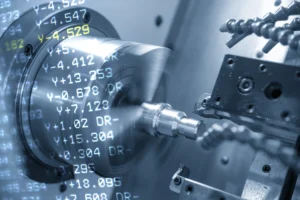
- Coordinate System: The system of coordinates, understood to understand the spatial position of a part in a machining project, typically includes X, Y, and Z axes, which sometimes include rotational axes like A, B, or C. This system enables accurate specification of every point on the part in the blueprint of the machining project.
- Title Block: The title block located at the top or bottom of the blueprint contains some basic information including part number, revision level, name of the manufacturer, material type, scale, and the date of the technical sketch. The availability of this information is of the utmost importance for the control and diagnosis of the machine tool CNC.
- Types of Views: Different kinds of views are usually included in CNC machining engineering drawings to highlight the front, side, top, and cross-sectional views of a part. In a way, each view serves to demonstrate the part from a different angle, making the shape more identifiable to the viewer.
- Detail Views: Traversing views are used to specifically focus on complex areas of a part, blow up the image to show exact dimensions and shapes. Thus these concepts help with learning the finer points of machine drawings.
- Manufacturer’s Notes: The producer’s notes have specific requirements and instructions to be followed during the machining of the part, including material specifications, machining methods, surface treatments, and heat treatment requirements. The information in these notes is of primary importance for the enforcement of quality and performance conformity of the part to the requirements.
How to Prepare Technical Drawings for CNC Machining
Step 1:
Design Phase: Start by ideating the part of the component that you want to fabricate. Think of the functions, choice of material, and any restrictions or list of specifications.
Step 2:
Create Technical Sketch: Draft a preliminary drawing or sketch of your part before proceeding further. These may be the drawings done desiring or using the CAD software.
Step 3:
Detailed Drawing: Make a detailed technical drawing of a part. Include specifications such as dimensions, tolerances, surface finishes, and geometric tolerances according to the requirements, ensuring the technical sketch definition is maintained.
Step 4:
Use Standard Symbols: Emphasize standard symbols and symbols from the code of aeronautical drawings for holes, chamfers, etc. by all people who take part in the process, like designers, machinists, and CNC operators, in order to make sure that everyone understands and no misunderstanding or errors will occur.
Step 5:
Dimensioning: Use proper dimensions to specify the size and location of the features that can be seen clearly on the part. Ensure the use of geometric dimensioning and tolerancing (GD&T) when such geometry is necessary.
Step 6:
Review and Validation: Revise and check the technical drawing for compliance. Confirm that all the dimensions and specifications reflect your design purpose and manufacturing abilities and also that they are compatible with the diagrams for machining.
Step 7:
CAD/CAM Integration: If you use CAD/CAM software, then check to see that there is a tie between the designing (CAD) and machining (CAM) stages. That is the tool paths are generated and the part program is written with the help of the technical drawing as well as with the drawing machine CNC.
Step 8:
Export to CNC Software: Lastly, import the final version of your drawing or model to your CNC software. As a result, this may imply that the drawing is converted into an acceptable file format like DXF or DWG for 2D drawings, or STEP or IGES for 3D models, according to the CNC’s technical requirements of your choice.
Step 9:
Toolpath Generation: Apply the CNC software to technical drawings of the part to achieve the toolpaths based on the cutting tools that are selected and the machining strategies. Optimize toolpaths for efficiency, accuracy, and good surface finish quality while taking into consideration projects which blueprints reflect the machining methods.
Step 10:
Simulation and Verification: Before machining the part, simulate the toolpaths so that you can identify any potential issues like collisions and toolpath errors. Check that the simulation is what you want to have by taking into account any drawing views you made.
Step 11:
Post-Processing: Please make sure that you are happy with all of the toolpaths before you post-process the CNC program and create g-code instructions specific to the machine. Make certain that G code is suitable for your CNC machine and controller, and that it is consistent with your engineer drawing easy style.
Step 12:
Setup and Machining: Setup the CNC machine with the toolpaths and G-code assistances. Machining according to the acceptable methodologies and protocols of safety during the machining process, to understand the drawing and accomplished CNC artistry of the finished product.
Adding dimensions, hole locations, and tolerances to the CNC drawings
When adding dimensions to CAD drawings, it is important to employ GD&T (Geometric Dimensioning and Tolerancing) procedures for accuracy. Emphasize critical dimensions by means of symbols, and mark extension and leader lines from the blueprint of object line pattern in a way to get the dimensions understood more clearly. This ensures that every measurement, including those on the machined surface, is as precise as possible, which will help in ensuring that the machining and assembly as per the intended design are made accurately.

Using hole locations and drafting symbols, which are clear, such as the drilling symbol, to depict the exact hole type does the job. Hidden line blueprints, lines that represent holes in the drawing but not necessarily on the surface, assist in the visualization process. Moreover, the hole’s positioning not only follows the extension and leader lines, but it also accounts for the accuracy of its placement, in relation to other features. This is essential for the component functionality.

Tolerances on CNC drawings are frequently shown on the drawing by specific drafting symbols, the range shown in the ‘typ’ (typical) applies to multiple dimensions without the drawing getting cluttered. Section lining symbols may be used for the interpretation of different materials in cross-sectional view pictures, thus machining necessities are seen clearly. These conventions, including the construction symbols on drawings, make it possible for the produced part to be in line with the specified requirements and to execute a smooth assembly by itself, retaining the design’s consistency.
Tips for Reading and Understanding CNC Machining Drawings
Understanding the Shape and Structure of the Part
It’s essential to correctly perceive the shape and construction of the part from the drawing. This encompasses the evaluation of the position in a graphical sense and its correlation with the overall design of the part. The essential make-up and functionality requirements of the part are understood by a keen examination.
Identifying the Datum of the Part
The datum of a part is necessary for maintaining the machining precision. The features mentioned include axis lines, centerlines of holes, datum planes, etc. The correct location of these datum points and surfaces is a precondition to getting the precise machining result.
Focusing on Key Dimensions and Tolerances
The drawing information on the dimensions, accuracy, surface roughness, form, and position tolerances is the main factor that influences the quality and performance of the part. These parameters direct particular maneuvers through the machining process, they are the backbone of the part meeting its design criteria.
Understanding Technical Requirements and Materials
The technical specifications and materials are used to determine the machining method and route of processing. These requirements are the basis for the selection of suitable machining processes that will guarantee the part performance per our expectations.
Analyzing Orthographic and Detailed Drawings
By studying the orthographic projections including left, right, and top views, as well as the sectional and detailed drawings, the part’s structure and contours can be understood entirely. This provides a way of building machining plans and easing material preparation.
Emphasizing Machining Tolerances and Precision Requirements
Especially surface roughness, tolerance of machining and precision requirements have a determinative influence on the part quality at the last moment. Thoroughly following these specifications will avert any mistakes while machining and increase the rate of acceptance of the parts.
Considering Special Treatments in Technical Requirements
The scheme may focus on special technical requirements like heat treatment or hardness requirements. These requirements have direct implications for the part’s functions. Knowing and getting ready for these special operations before machining is another essential step toward guaranteeing the quality of the part.
Use of CAD Software in Preparing CNC Machining Drawings
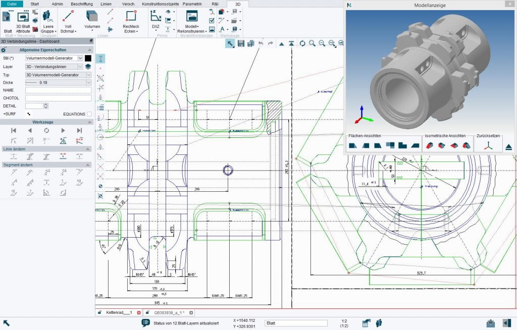
In the manufacturing field, CAD software has now become a must-have tool in the work of designers, especially in CNC machining drawings. Using the software (e.g. AutoCAD, Fusion 360, and SolidWorks) designers can rapidly and accurately draw 2D and 3D drawings of parts. The high precision contributes to better quality designs and fewer reworks during production which in return increases unit efficiency. A third critical characteristic of CAD software is its function of guiding engineers in optimizing machining paths. This function helps save costs and improve the quality of machining. Through the process of simulation, the designers can anticipate possible problems and make changes before the actual machining, to avoid the occurrence of difficulty in the production process.
Conclusion
CNC machining drawings are essential for precision manufacturing, bridging the gap between design and product. They guide the machining process with detailed specifications, utilizing CAD software for efficiency and accuracy, thus enhancing production quality and efficiency.